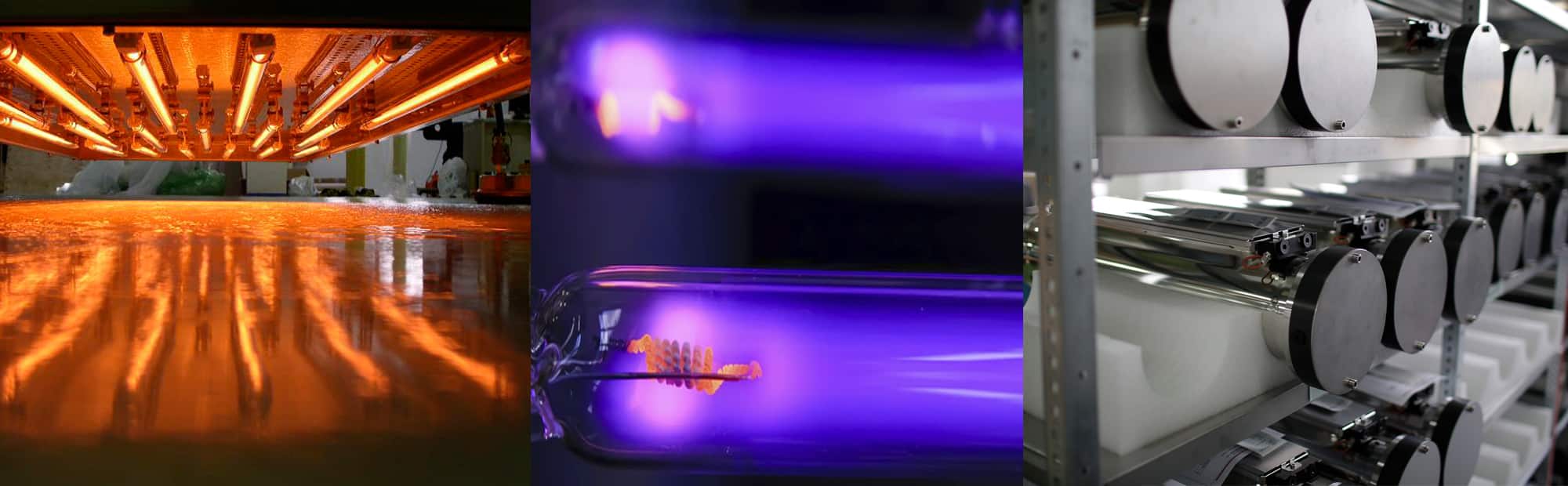
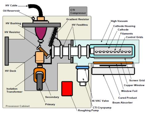
The EB equipment creates an electron beam much as the beam is produced in conventional electron tubes used for high power radars or radio and television wave transmission. The electrons originate from tungsten filaments which are electrically heated.
After the electrons are emitted from the filaments, they are accelerated to high velocities by the force exerted on them by a high voltage electric field. All of this takes place in a stainless steel vacuum chamber. The accelerated electrons have so much energy that they are able to pass through thin metallic foils which are used as "E-beam windows" to separate the vacuum chamber from atmospheric pressure. The window foils are often made from 0.006 inch thick titanium. Outside the vacuum chamber the electrons hit the printed web as it passes through the BroadBeam dryer. The actual region where the interaction occurs is kept filled with nitrogen gas, because the oxygen in normal air inhibits the favorable joining of molecules.
As electrons have a mass and behave as particles and not waves they are not included in the electromagnetic spectrum like photons. The range of voltage of an electron beam machine used in industrial curing applications is between 80 to 300 kV
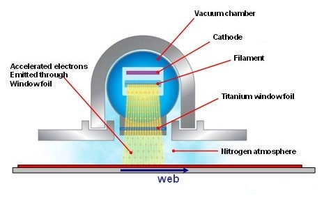
In a typical system, high voltage is applied to tungsten wire filaments inside a vacuum chamber. This voltage heats the filaments to a point where a cloud of electrons is generated. By differing voltage between the cloud of electrons and the titanium exit window of the emitter the electrons are drawn toward the window with great speed (in general 50 to 70 % of light speed) and energy. The electrons continue on through the titanium foil of the window and out of the emitter where they impact the coating. As they exit the emitter the electrons impact the coating passing under that window and cause polymerization and cross-linking. A titanium window foil supported by a water-cooled copper window is used to isolate the vacuum environment of the cathode from the reaction chamber. Excess electron energy that passes through the reaction chamber is absorbed by the beam absorber which can be a chill roll or cooling plate on a lift table assembly. The beam absorber is also water cooled.
Electron beam curing occurs as the result of energy transfer from the accelerated electrons. Electrons penetrate the product resulting in free-radical polymerization of coatings causing instantaneous curing. Nitrogen is used in many electron beam processes to displace oxygen and reduce ozone generation. Nitrogen inerting is mostly used with curing processes and is entirely contained in the reaction chamber of the machine.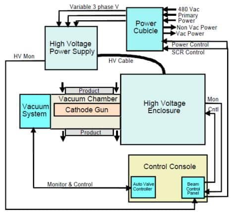
The transfer of energy from the electron beam into material is specified completely by four parameters:
- Depth of penetration
- Absorbed dose
- Beam uniformity
- Throughput
Penetrating range of the electron beam is related to the accelerating voltage and the density of the processed material. Higher voltage causes deeper penetration, and denser material reduces the depth of penetration. The Depth Dose Curves are convenient aids for estimating the penetration depth.
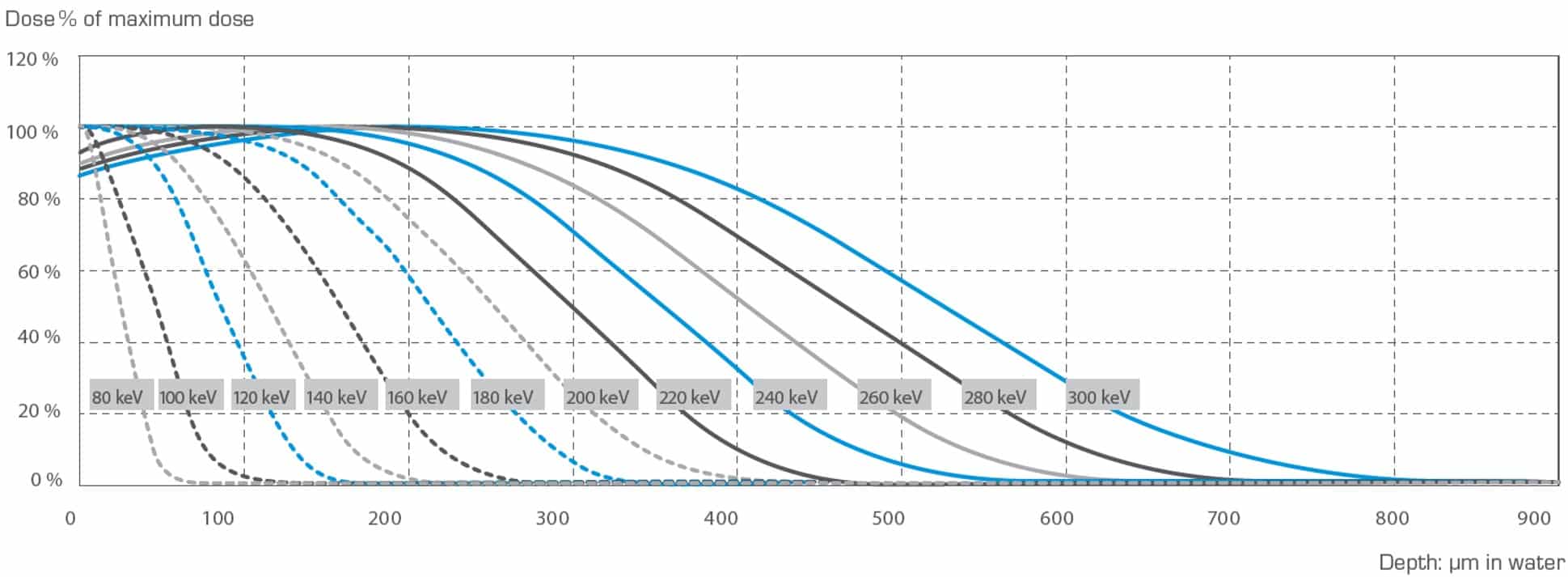 Penetration into materials of different density can be estimated by multiplying the penetration depth, found from the normalized curves, by the ratio of the density of water to the density of the material. At accelerating voltages of 150, 180 and 250 kV respective curing depth of 86, 138 and 277 g/m2 are achieved at 80 % ionisation.
Absorbed dose is defined as the amount of energy deposited into a specified mass of material. The unit of absorbed dose is kilogray (kGy), defined as the number of joules (J) of energy deposited into 1 kilogram (kg) of material. An older unit is megarad (Mrad).
1 kGy = 1 kJ/kg
1 Mrad = 10 kGy = 10 J/g = 2,4 cal/g
Heating of water 1 degree 1 cal/g
Evaporation of water 540 cal/g
EB-curing of lacquer approx. 10 cal/g
At a fixed electron accelerating voltage, the dose is directly D [kGy] is proportional to electron current I [mA] and inverse to web speed v [m/min] as follows:
D = k x I/v
The k factor is depending on the equipment and the accelerating voltage. The formula above shows:
Radiation is only produced by an electron beam processor when the machine is running. Accelerators work on the same principle as a television tube: when it is off, you do not have neither picture nor sound. Radiation emission levels are very low and are managed by the equipment design and operating practices.
Most electron beam processors are self-shielded, meaning that the radiation is contained in the reaction chamber and integral shielding. This is accomplished through the use of lead lining and having no line of sight into the processing area.
Electron beam machines are designed to be fail-safe. Radiation monitors are installed on the machine to monitor the outside environment radiation levels. These monitors are wired directly into the operating system to automatically disconnect power to the machine when an alarm is tripped. Potential radiation exposure points occur at openings in the machine near the product path or maintenance access areas.
It is also important to mention that the coating submitted to the EB radiation will not be considered as radioactive.
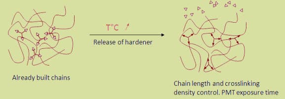
E-beam drying makes use of the ability of electrons to interact with the atoms and molecules of materials in ways which cause the material properties to change. Special solventless coatings are formulated so that the interaction between the electrons and the coatings produce favorable functional and aesthetics properties in the dried product.
A simplified way to visualize the "drying" process is to imagine the coatings to be mixtures of atoms and molecules which are not tightly connected to each other in the "wet" state. When these "wet" products are passed through an E-beam dryer, the beam's electrons transfer energy into the atoms and molecules, causing them to break apart and then join to other atoms and molecules.
By this process, individual molecules become linked together and form a large bound molecular structure containing all of the "loose" atoms and molecules of the "wet" product. This connecting of molecules is the mechanism producing favorable properties of the dry coatings.
In general, ebeam benefits that printers and converters have documented include improved product performance, superior product consistency, higher process throughput and greater energy savings.
Specific to thermal drying, ebeam curing offers several significant benefits, including the following:
- Ebeam systems take up much less space than ovens, which can, in some cases, be hundreds of cubic feet in size. Some converters that have replaced ovens with an ebeam system find enough floor space has been freed up to put in a new line.
- Ebeam systems generate very little heat in the substrate being targeted, making it a solid choice for printers and converters over thermal and UV curing (and, it sometimes is the only option) for treating heat sensitive materials like thin films (such as those found in shrink sleeve labels).
- Ovens require an enormous amount of energy and are staggeringly expensive to operate and maintain. There have been studies that have shown that, in some cases, an ebeam system requires up to 95 percent less energy than the oven it replaces.
- Finally, ebeam systems help contribute to workplace safety and comfort. With no need to remove solvents from inks and coatings, ebeam curing eliminates the volatile organic compounds (VOCs) that are associated with thermal drying.
Specific to UV curing, ebeam curing also offers several significant, but different, advantages. These include the following:
- By definition, UV curing requires photoinitiators to complete the curing process. Photoinitiators are toxic and run a slight, but nonetheless real, risk of migrating into food. Ebeam curing does not need photoinitiators to work and thus poses no potential for migration. This makes ebeam extremely popular among food package printers and converters.
- Ebeam curing has proven to work particularly well when curing thick, opaque and/or high density Ink and coating layers vs. more conventional UV curing methods.
- Like thermal drying, UV curing produces a significant amount of heat. In certain cases, ebeam curing has been shown to require up to 80 percent less energy than UV curing.
- Unlike UV bulbs, whose power declines over time, ebeam curing offers extremely precise processing, with a stable energy output that does not drift over time.
Ebeam continues to be a growing topic among printers and package converters because it instantly dries - or more accurately, cures - ebeam friendly inks, coatings and laminate adhesives on paper, film, paperboard or metal. It is a growing alternative to oven (thermal) drying and ultraviolet (UV) curing for a number of reasons discussed below. Web offset printing presses have been equipped with ebeam units for many years. Ebeam curable ink technologies also exist for flexographic and gravure printing. As is the case in most of the printing industry, Ebeam curable inkjet is generating significant interest and is very likely to grow rapidly. Plus, in recent years, printers and package converters have discovered that ebeam can be used not only to cure inks, coatings and adhesives, but also as a useful tool to give extra "eye appeal" to packaging.
As the printing, label making and converting industries grow and become more versatile, so does ebeam. Beyond curing and crosslinking, a recently developed 4in1 converting line allows package printers to utilize ebeam systems to create innovative package designs. Visual enhancements offered by an ebeam package decorating system include overprint coating, laminating, cold foil transfer and Cast & CureT holographic embossing.
Ebeam provides instant curing of coatings and adhesion of laminates to a packaging surface, providing a high gloss and inherent durability that is not possible with other curing technologies. Packagers take advantage of increased package brightness and strength capabilities to give products a new visual pop, while reducing package abrasion and breakage risks.
With cold foil transfer, an ebeam curable adhesive is applied to a substrate in registration with printed graphics and then is ebeam cured with an overlying metalized film. The metal transfers to the cured adhesive areas, producing a strong visual metallic effect. Nearly any type of hot or cold stamping foil may be used in an ebeam cold foil process.
Finally, Cast & Cure is a decorative coating process that integrates "casting" and "curing" to provide a consistent high quality finish. It can generate ultrahigh gloss, matte and holographic images onto a variety of substrates. This environmentally friendly process helps make packages more recyclable by eliminating the laminated, metalized films used in traditional holographic processes. Additionally, this casting film is reused multiple times, achieving substantial cost savings.
Ebeam package decorating systems are designed for use with web printed packaging materials, including flexible packaging, folding cartons, labels and multiwall bags. These systems work at high speeds, are compatible with wide web widths and generate low substrate heating, which is important when utilizing sensitive flexible packaging materials, such as thin films.
People unfamiliar with ebeam technology are amazed by the concept of curing surfaces by altering molecular structures instead of thermally evaporating solvents or water. They even are more shocked when they learn that this "radical" technology is more than 40 years old! The reason ebeam continues to grow in popularity is twofold: first, the systems and ink/coating/adhesive formulations necessary to achieve ebeam curing continue to fall in price as the technology gains popularity and second, ebeam offers a number of key benefits over thermal drying and UV curi
The potential applications targeted for EB curing in the Coil processing industry are:
- Primer and backing coat
- Any color or metallic aspect for top coats
- Clear coats
EB Curing Process
Electron beam curing process principle is different than curing processes with photons. Industrial curing process with photons (UV) is a "non-ionizing" curing process and EB curing is a "ionizing" process. The energy involved in EB process can directly or indirectly form ions and generate electrons while traveling through a substance or can create "free radicals" by moving the electrons of the substance to a higher-energy orbital. Those ions or free radicals (exited atoms/molecules), the precursor species of the curing process, are then directly generated by the EB in the substance to be cured and the use of photo-initiators is not required. The absence of photoactive fragments in electron beam curable coatings results in greater stability..There is also greater penetration of the radiation (greater depth of cure) with less interference from pigmentation.
In the process of polymerization, the unsaturated molecules of a low-molecular compound (monomer) combine with one another, thereby producing a polymer (high molecular weight compound). The molecules of polymers can be two-dimensional (flat structures), or three-dimensional (spatial polymers). Ionization radiation is capable of stimulating both the process of combination of monomer molecules into polymeric chains and the process of cross-linking creation, that build a three dimensional structure.
Non EB cured
EB Cured
As a result of the cross-linkage, structures with higher mechanical and thermal resistance are formed, that are insoluble in organic solvents. Clear coatings of up to 500 microns and pigmented coatings of about 380 microns can be cured with EB equipment depending on the dose available.
Some data comparing solvent based to EB curing
Advantages of EB Curing
- Environmentally friendly due to a 100 % solid system.
- EB generates absolutely no emissions.
- No substrate heating.
- Very low energy consumption.
- High Speed of cure: Substantial production increase compared with conventional heat treatment methods and UV-technology, also with pigmented layers.
- Low space requirement. Integration into existing coil coating lines without any problems.
- Exact repeatability of production conditions is obtained due to high dose accuracy. There is also no wastage when starting up and shutting down the plant.
- High levels of fastness and outstanding surface properties.
The surface of a EB cured coating is:
Free of harmful substances
Non-ageing
Weather-resistant
Hard, Scratch Resistant
Colour-stable
Resistant to organic solvents
Resistant to a wide range of chemicals.
Attention should be particularly put on:
- Ozone formation: a controlled atmosphere with less than 200 ppm oxygen is required.
- Various safety and handling aspects.
- Higher coatings prices
The entire process is completed in the time that it takes for the strip to pass through the electron beam. EB equipments are powerful enough to cure at highest speed (500 mpm). At these speeds, the entire process is completed in 0.024 seconds.
- Minimal Space in Line. The EB equipment length can be very short because the curing occurs so fast. Overall in-line length of the BroadBeam processor is less than 3 meters.
- No Solvents, No VOC's. Solvents are not used in the coatings. Unlike conventional coatings, the process does not require the removal of solvents in order to create a dry product. In other words, all of the chemicals in the "wet" product remain locked into the "dry" product. This is the reason that no VOC's are produced, and no incinerators or other devices are needed to treat pollution.
- High Electrical Efficiency. The process for creating the electron beam is highly efficient as is the interaction of the beam with the coatings. The electrical energy is carried directly into the coatings by the electrons, in contrast to heat set dryers in which a large volume of air must be heated and must in turn heat the product. Electron beam dryers can be as much as 100 times more efficient than thermal dryers. This high efficiency contributes to the favorable cost comparison to heat set printing.
- No Strip Heating. Because the electrical energy goes directly into the coatings, and the strip doesn't dwell in a hot gas, the temperature rise of the strip is typically less than a few degrees.
- Functional and Aesthetic Characteristics. High gloss, scuff resistance, depth of color, and strong bond to substrate are some of the best known properties of E-beam cured coatings. Not as well known is the way in which these features relate to recyclability of the finished product.
No, not always. As has been mentioned, ebeam is the "goto technology" if there is food packaging involved? sensitive substrates that might be damaged by heat? or thick and/or opaque inks, coatings or adhesives that need to be cured. But, not every printing process benefits by using ebeam curing. For instance, PostPress magazine - and most other commercial printing jobs - wouldn't benefit by having its inks cured using ebeam technology.
The major methods of heat transfer are:
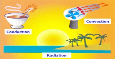
Conduction: Heat transfer is by direct contact between the source and the object.
Convection: Heat transfer is by a flow of liquid or gas which is itself heated by a heat source.
Radiation: Heat transfer is by the emission of radiation from a hotter object such as the sun, an open fire or an infrared lamp to its cooler surrounding environment. Objects which receive this radiation from the heat source absorb it and become hotter. InfraRed (IR) radiation is an electromagnetic phenomenon, and it is a form of wave motion.
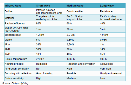
All bodies with a temperature above absolute zero emit InfraRed radiation. The heat loss or gain by infrared radiation can be significantly more than that from other modes of heat transfer such as convection and conduction. IR is transmitted by line-of-sight, and, like visible light, can be focused (concentrated) or reflected. The energy received at a surface from IR is a function of the distance from the source (emitter) and the angle of radiation incidence. The energy transferred will be greater if the object to be heated is perpendicular to the IR emitter. For industrial applications, infrared radiation is useable within the range of 0.76 to 10 ?m. IR is usually divided by convention into three classifications:
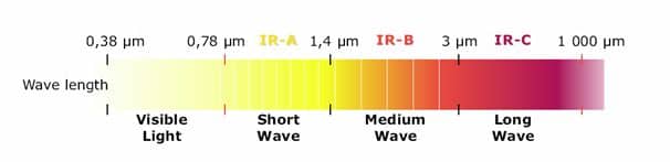
- Near InfraRed or Short-Wave InfraRed, from 0.76 to 2 ?m
- Medium-Wave InfraRed, from 2 to 4 ?m
- Long-Wave InfraRed, from 4 to 10 ?m
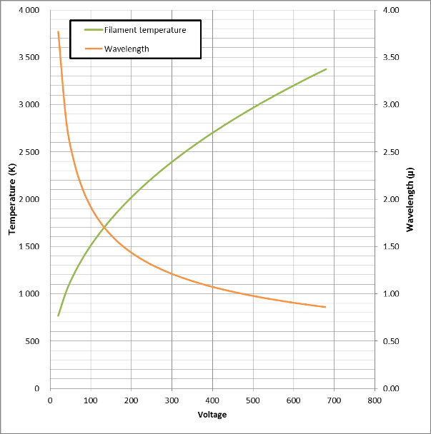
The wavelength of infrared radiation depends on the temperature of the emitter. The peak wavelength gets shorter with increasing emitter temperature. At surface temperatures below 650°C, virtually all of the emitted radiation is in the infrared region of the electromagnetic spectrum. Above this value, more of the radiation emitted by the surface is in the visible spectrum (380 nm to 760 nm).
This behavior may be observed, for example, when a piece of steel is heated electrically or in a flame. Initially, the steel emits no light but with further heating glows a dull red. With increase in temperature it becomes brighter and the color shifts from red to orange to yellow and finally to white.
The infrared radiation striking a surface is either reflected, absorbed, or transmitted. The penetration ability of infrared radiation also varies with wavelength. Generally, the shorter the wavelength the more penetrating power the radiation has. The property that determines the amount of infrared that is absorbed by a surface is referred to as absorbance.
The emission spectrum of the infrared heater has in general to match with the absorption spectra of the material to be heated.
Radiant efficiency is highest for short wavelength sources. This behavior results because the heat transfer by the convection and conduction modes increases only in direct proportion with temperature increase, while heat transfer by infrared increases as the fourth power of temperature as governed by the Stefan-Boltzmann law.
Another important factor for efficiency is the use of parabolic reflector in order to guarantee a good diffusion of the energy on the substrate. Choice of polished extruded aluminum is key for further energy transfer and energy savings.
High-intensity NIR or SW infrared emitters can operate at up to 3000°K. When focused and concentrated they have the ability to surface melt almost all metals.
Focused, high-intensity infrared emitters are well suited for rapid heat treatment, with accurate power control, of low thicknesses substrates such as metal coils.
InfraRed, like other forms of electromagnetic radiation such as light, travels in a direct line at the speed of light through a vacuum as well as through a medium such as air.
The maximum amount of infrared radiation is emitted by an ideal radiator, called a black body, and is proportional to its surface area and the fourth power of its surface temperature rendered in absolute units. This has been expressed as the Stefan-Boltzmann law of radiation: E = k (T4 - T04) (Stefan-Boltzmann law) where E is radiated energy, T is the absolute temperature of the black body, T0 is the absolute temperature of the surroundings, and k is a constant.
Determining the infrared emission from real bodies, or gray bodies as they are referred to, requires the introduction of another proportionality factor called emissivity. Emissivity is a property of the material surface and, though it generally depends on temperature, is usually taken to be a constant. The value of emissivity varies from zero for an ideal reflector, to 1.0 for a black body.
For real or gray bodies, the Stefan-Boltzmann law becomes: E = ?k (T4 - T04). ("?", is the emissivity for a real body, at system temperature).
InfraRed systems can be used in coil coatings line for the curing of:
- Primer and backing coat
- Top coat
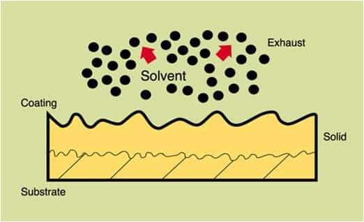
Curing is the oxidation or polymerization cross-linking chemical reactions which occur in addition to solvent removal from coatings.
When coatings are dried in a conventional convection oven, the paint must be dried slowly to prevent the formation of a solid skin on the surface. If a surface film forms, additional solvent, as it is heated and vaporizes, can cause blistering of the skin, resulting in a surface defect.
IR radiation can penetrate thin coatings and heat the underlying substrate. The substrate then conducts heat into the coating, curing the coating primarily from inside to outside (Some IR will be reflected from the substrate back through the coating, where it will either be absorbed or transmitted back to the atmosphere of the oven). This mechanism allows much faster curing rates with IR ovens.
The solvents from coatings which contain organic solvents can become explosive. Air flow within an IR oven for these drying applications is essential to avoid vapor accumulation. In general, cooling air is differentiated from process air and hot air to reach a maximum of 25 % LEL level is blown inside the oven.
The air saturated with solvent vapour is then sent to a regenerative thermal oxidizer. Different scenarios can be studied to minimize energy consumptions.
The colour of the absorbing surface is another factor that can be important in InfraRed heating. Dark colors, such as black, typically absorb infrared more readily than white or light colors. This behavior is observed more strongly at higher source temperatures.
IR ovens for curing coatings on metal substrate are designed and produced with SW/NIR because they provide the high intensity energy required to heat the metal surface rapidly. The percent electrical energy that is converted to radiant energy is higher with shorter wave lengths.
SW/NIR InfraRed heaters are often used as "booster" oven sections either before or after conventional convection oven sections. Their use can often allow significant line production speed-up due to the high intensity of the radiation.
InfraRed systems can be used in metal processing applications for efficient drying of :
- Passivation / antifingerprint dryer on galvanizing line
- Insulating coating on silicon steel process
- MgO slurry evaporation in GO electrical steel line
- Chemical treatment in coil coatings line
- Replacement of squeeze rolls
InfraRed has a distinct advantage over gas convection ovens for drying processes, as IR can apply heat quicker than can a convection oven. Quicker heating results in shorter processing times and smaller ovens.
Water exhibit behavior for short-wave infrared radiation that is very similar to that observed for visible radiation. Virtually all of this type of radiation is transmitted; i.e., water is transparent to light and short-wave radiation. However, infrared radiation above 2 µm is strongly absorbed by water.
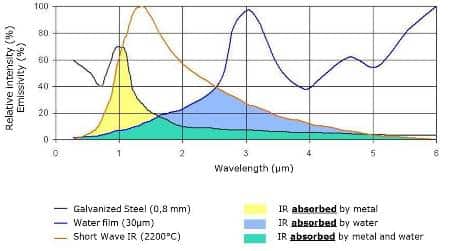
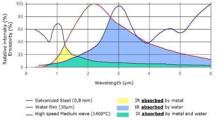
For water, very low absorption values are seen at wavelengths below around 2 µm, but large absorption values are observed at longer wavelengths to about 3.3 microns. This behavior suggests that infrared radiation emitted between 2 to 3.3 microns will be readily absorbed and thus be effective in drying.
The missing energy will come from the substrate itself that will conduct the absorbed energy to the surface and contributes to the evaporation. For efficient drying, the air used for cooling the lamps is in general used for adding convection effect and required ventilation to extract water molecules.
Yes.
We can design InfraRed equipments equipped with Near InfraRed lamps. These lamps have higher filament temperature (up to 3000°K) and shorter wavelength. The penetration of the radiation is quicker and may induce shorter drying / curing times.
Nevertheless the higher temperature of the filament has a strong impact on the life length of the emitters. We are working actively with our lamps manufacturer partner to achieve soon life length of 5000 hours or more. Today unfortunately, the life length is really depending on the usage of the equipment and it is difficult to give warranty.
The process of Ultra-Violet or UV curing is defined as the hardening of a liquid form of material when exposed to ultra-violet energy. The particular substance to be processed may vary widely depending upon its application and final use but basically it is composed of pigments, photoinitiators, additives and binders (monomers and oligomers).
Ultra-violet (UV) curable coatings require a 'high intensity' source of UV energy to initiate a chemical reaction. This reaction initiates and completes the hardening of UV coatings in fractions of a second.
The electromagnetic spectrum, of which UV forms a small part, is expressed in units of wavelengths and frequency (measured in Nanometers: 1 nm = 10-9 m). Longer wavelengths form radio and microwaves, and reducing wavelengths descend through infrared, visible light to UV and beyond. UV wavelengths are extremely short. They lie between 200 and 380 nanometers and are the most suitable UV wavelengths for the hardening of UV curable inks and coatings.
The UV spectrum is divided into three domains:
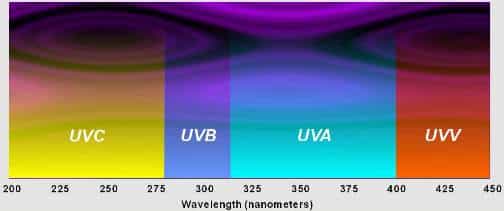
UV-C: 200-280 nanometers.
These high-energy rays, essential for the curing (or polymerization) of UV coatings, ensure a complete and fast reaction. This range is essential for surface curing of the ink or coating.
UV-B: 280-315 nanometers.
This range helps to maintain an extensive reaction. Due to its longer wavelengths, this UV energy enables a deeper penetration of the liquid form.
UV A: 315-380 nanometers.
This UV energy is the closest to the visible light part of the electromagnetic spectrum and is responsible for stimulating a deeper curing of the more substantial layers of coating film.
To understand better the process of UV curing it is important to understand the differences between the drying of conventional coatings and UV curable products.
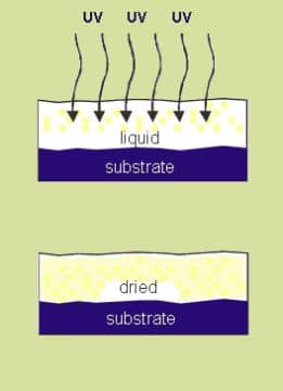
Alternatively, UV curable products are converted to a solid state through the chemical process known as polymerization. This process starts when the coating film is exposed to UV energy and at this stage the photoinitiators contained within the UV coating are transformed into free radicals (atoms or groups of atoms containing a free electron).During the UV curing process, these radicals constantly seek a partner and in this case, the partner is represented by the oligomers and the monomers contained within the UV coating. The oligomers and monomers therefore become bound together and included within this binding process are contained the pigments and other additives within the polymer chain. The concluding effect of the UV curing process is that all of the elements within the UV curable product become bound into a strong polymer through crosslinking and it is at this stage that UV curable coating is fully stable. When this is the case, the UV curable coating is represented as a solid structure with a completely uniform surface.
Unlike conventional coatings there are no compounds to be oxidated or evaporated. Instead all of the reacted components participate in the instantaneous polymerization. Therefore, 100 % of the quantity of material remains in the cured film. This also makes UV curing technology one of the cleanest technologies from an environmental point of view
- Solvent-free formulations systems.
- Productivity: short curing times, high production speeds, and very compact units.
- Low energy costs.
- Minimal heating of the substrate.
- Ability to add easily a new coating section (3rd layer) to give extra functionalities to the top coat: dust pick-up, chemical resistance, anti graffiti..
- Increase versatility of a coil coating line
- Solvent-free paint and varnish systems: Preserve the environment
UV lamps are composed typically of a quartz tube, the inside of which contains mercury within an inert atmosphere). The body of the lamp is made from high quality quartz, assuring a minimum transparency of 90 % UV energy. The quartz body must be able to resist an inner temperature of up to 1100 ºC. Temperatures of up to 900 ºC are reached on the surface. To avoid damaging the lamp an effective heat management system has to be installed.
Vacuum tight tubes with sealed-in electrodes on both ends are used for the gas discharge. The filling consists of an ignition gas (mostly argon) and of liquid mercury spheres. A glow discharge is caused if the voltage above the cold electrodes is sufficient. When the electrodes are heated up, electrons are released out of the cathode. These cause a rapid growth of the electrons via shock ionization of the filling gas. There is an arc discharge in the noble gas. Electrical energy is transferred to the light arc via kinetic energy of the electrons. Impulses distribute the energy, the tube is heated up and the mercury evaporates. Formation and characteristic wavelengths of the UV energy depend specifically on the type of additives (e.g. mercury) used and the amount of energy absorbed. At the present time, mercury is the most commonly used additive in UV lamps as it emits UV energy over a very large wavelength spectrum, therefore providing the potential to cure the maximum number of colours typically used by printers in the UV graphic art applications.
In particular applications, the use of doped lamps (lead, iron, cobalt, gallium,.) can be very efficient. These metals cause the emitted spectrum to change, often to a more specific band of wavelengths. Whilst not as general in purpose as the mercury vapor spectrum, in certain cases this changes the output of the UV energy to fit better with the transmission characteristic of difficult colours or absorbance of specific photoinitiators.
UV mercury lamps do not usually suddenly fail. Generally, such lamps can operate for thousands of hours. However, a regular decline in UV energy efficiency can be noticed over a period of time. Towards the end of a lamp's usage life, the UV lamp can give the impression of functioning normally, but in fact the emission of UV energy is reduced. Also a deterioration of the quartz surface of the lamp, normally noticed by the lamp becoming more opaque in appearance, will cause a filtration of the required UV energy (mainly shorter wavelength) and therefore lower its output.
The lamp's lifetime depends mainly on the following parameters:
- Quality of the lamp
- Heat management
- Cleanliness of the lamp
- Frequency of switching on and off
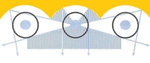
UV energy received directly from the lamp represents typically only about 45 % of the UV energy received at substrate level. The presence of reflectors within the UV system provides for the recovery of the remaining UV energy. Since efficient reflectors are required to reflect about 55 % of UV energy, this explains the great interest of the UV equipment manufacturers to choose and design materials and equipment with a very high reflective surface for UV energy. Aluminum is one of the most reflective and readily available materials reflecting around 90 % of UV energy. Being sensitive to high temperatures, the surface of aluminum has to be specially treated to ensure efficiencies are maintained over a long period of time.
Importance of the shape of the reflector:
Over the past few years, reflectors with an interference coating have been gaining more and more acceptance. The reflective layer of the so called dichroic reflectors is composed of approximately 60 various metallicoxide layers and is a highly efficient reflector of UV energy in the required UV spectrum. Dichroic reflectors or cold mirror reflectors as they are also known, reflect the UV energy in the range 200 to 450 nanometers at around 98 % efficiency whilst allowing the infrared energy to be transmitted through the dichroic coatings and the cold mirror glass.
The importance of reflectors within a UV system should not be under-estimated. So much importance is placed on ensuring that the UV energy source, the lamp, is maintained in the best possible condition and changed regularly. Many current users of UV systems around the world neglect the operating conditions of the reflector and, where this equipment is responsible for reflection of around 55 % of the UV energy source, this very often means that UV lamps are being changed more frequently than is necessary to compensate for the poor condition of the reflectors.
All manufacturers of UV LEDs packaged for UV curing provide a specification of the irradiance or peak irradiance under the lamp, and typically at specific distances from the lamp face (watts/cm²). The model of the LED identifies the nominal wavelength.
But, what about exposure at various speeds? Many LED curing systems position the LEDs at 2 to 20 mm from the work surface. What if the distance between the lamp and the work is too small for an integrating type radiometer or dosimeter? Or, what if one simply can’t be sent through the system?
If you have a very thin, probe-type radiometer with a wavelength response that covers the particular LED, then you may be able to "map" the irradiance profile, as in Figure 1.
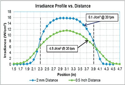
Figure 1. Series of static irradiance measurements made with 15W/cm²|44mm|385nm UV Lamp at 0.1-inch intervals, at 2mm distance and 0.5-inch distance.
This involves re-positioning the probe carefully at many equally spaced points and making the following calculation: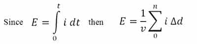
Where E is the exposure, in J/cm²;
v is the desired velocity in inches/second (or mm/s);
i is the irradiance at each measurement point; and
?d is the increment of distance in inches (or mm).
The profile is unlike most medium-pressure mercury lamps that have a sharply-peaked profile and irradiance that "tails" on either side of the peak. The shape of these profiles and the "tails" make it difficult to calculate exposure (Figure 2). To find the area under the curve, which is proportional to exposure, we are usually forced to use an integrating radiometer.
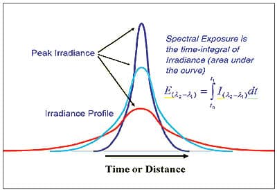
Figure 2. Characteristic irradiance profiles of tubular lamps with focusing reflectors — typical of medium-pressure mercury and additive types of lamp.
LEDs are arrays of packed LED dies, so they usually have a characteristically "soft" irradiance profile. Profiles will be similar, even if the array has some concentrating optics applied. When examining the typical LED profiles, observe that the space above the curve inside and the space below the curve outside of the 50% points are similar – they have similar areas. This leads to a very rough approximation:
E = Ip x D/v
E is exposure in joules per cm² (J/cm²);
Ip is peak irradiance under the lamp head in watts per cm² (W/cm²) at a specific distance;
D is the distance (in the travel direction) between the 50% irradiance points, in inches (or mm) [This is approximately the width of the LED array and may be similar to, but smaller than, the window dimension]; and v is the velocity of the surface under the lamp, in inches per second (or mm/s).
This method gives a good approximation of the exposure under an LED, or several LEDs, when a dosimeter or an integrating radiometer is not practical or available.
Units are customized for all applications to meet each customer's exact requirements.
- Effective heat management
- High efficiency of aluminium reflector technology
- Safe operator environment
- Long lamp life
- Compact design
- Operator terminal with input data and alarm logging.
The following are a few examples of what UV coatings can target today:
- Adhesion promotor for plastic films on metal substrate
- Antifingerprint and Drylube varnishes
- Added value Clear coat (3rd layer) / New functionality
- Coil Coating Pretreatment primer
- Coil Coating Backing coat (foamable, glueable)
- Insulating coating (C3 and C5 grades) for electrical steel
- Temporary protection for tubes and sheets
- Scratch-resistant coatings
- UV-powder coating primer and top coats
- Weldable primer for automotive industry